
Why Co-Packaged Optics Uses External Lasers Instead of Integrated Sources
On-chip lasers for CPO are the holy grail, but a near-term pragmatic approach is to keep lasers external for thermals and reliability. A look at the physics, implementation, and solutions.

Welcome to a 🔒 subscriber-only deep-dive edition 🔒 of my weekly newsletter. Each week, I help investors, professionals and students stay up-to-date on complex topics, and navigate the semiconductor industry.
If you’re new, start here. See here for all the benefits of upgrading your subscription tier!
As a paid subscriber, you will also have access to a video explanation of this post, an executive summary with key highlights, and a google drive link to this article so that you can parse it with your favorite LLM to mine insights best suited to your needs.
CPO is not a new idea, and has been around for the last decade. I recommend Asianometry: The AI Bandwidth Wall & Co-Packaged Optics, if you are unfamiliar with the basic concept. For a long time, CPO has had to deal with challenges that involved laser integration.
The core problem is thermal. Modern switch ASICs dissipate hundreds of watts of power. Laser sources require precise temperature control to maintain stable wavelength, output power, and reasonable lifetimes. Placing these temperature-sensitive components directly adjacent to high-power switch silicon creates a fundamental conflict.
The second challenge is reliability and serviceability. Field data from hyperscalers shows that laser sources are among the top three failure modes in optical systems. In traditional pluggable transceivers, a failed laser means swapping out a front-panel module. In co-packaged optics, the laser is integrated with the switch ASIC itself. A laser failure would require replacing the entire package, an expensive and disruptive operation that undermines the business case for CPO deployment.
The industry’s solution to both problems is external lasers. By relocating laser sources away from the switch ASIC to front-panel modules, CPO systems can maintain lasers at controlled temperatures while preserving hot-swap serviceability. This approach, standardized through External Laser Small Form-Factor Pluggable (ELSFP) specifications, has become the practical path forward for CPO deployment.
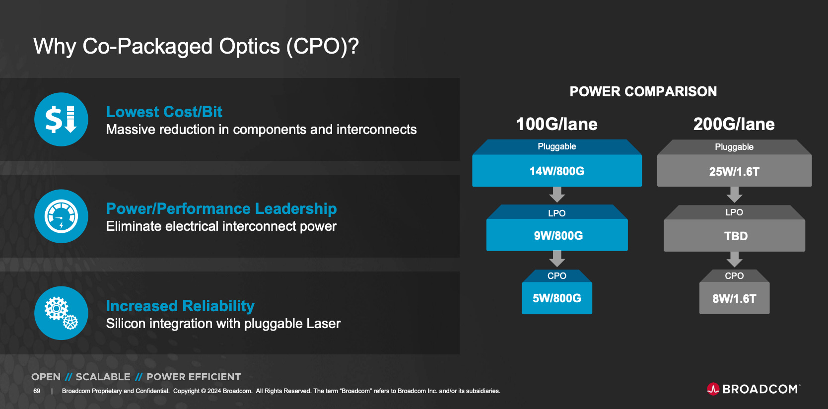
Today, CPO is a reality and it is not just speed that is a benefit; even at 800G interconnect speeds (100G/lane), there are significant energy savings. As speeds go to 1.6T and beyond, CPO becomes the primary technology of choice.
In this post, we will dig deeper into how external lasers solve CPO’s thermal and reliability challenges. We will cover:
Where to put the laser?: The architectural tradeoffs between traditional pluggable transceivers and co-packaged optics
Temperature Sensitivity in III-V Laser Wavelength: Why heat causes wavelength shifts and channel interference
Impact of Temperature on Lasing Threshold and Efficiency: How elevated temperatures degrade laser performance
Lifetime Degradation at High Temperatures: Exponential reduction in laser operational lifetimes
For paid subscribers:
Laser Failure Rates: Field data from hyperscale datacenter operations
Solving the CPO Serviceability Problem with ELSFP: How external laser modules preserve hot-swap capability
InP Distributed Feedback Lasers for CPO: The laser technology used in production CPO systems
CPO Measured Reliability Performance: Lab stress test data from Broadcom
Laser sources: Key players: Best solutions for external lasers, and evolving ones
Read time: ~12 mins
Where to put the laser?
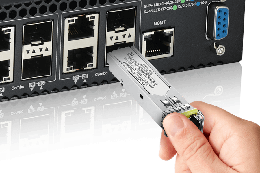
Laser sources are required to convert electrical information into the optical domain. Pluggable optics today have the laser source in a small form factor pluggable (SFP) device that has a full optical transceiver in a compact connector that plugs into the front of the rack.
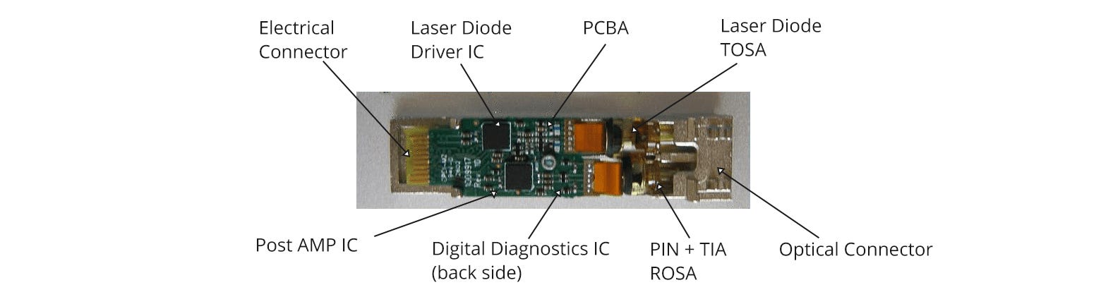
The internals of an optical SFP transceiver are shown below. It consists of a transmitter optical sub-assembly (TOSA) consisting of a driver IC that drives a laser diode. The receiver optical sub-assembly (ROSA) has a diode photodetector and a trans-impedance amplifier (TIA) that amplifies the detected optical signals. If there are any optical failures, this whole connector and optical fiber assembly can be easily swapped out.
But CPO takes this optical transceiver and integrates it next to the switch ASIC on the same package. In an ideal scenario, the electrical-optical conversion that was happening in the connector, now happens in a silicon photonics (SiPho) chip right next to the silicon ASIC. This dramatically reduces the electrical interconnect distance needed between the optics and ASIC. The electrical DSP used in optical transceivers to compensate and correct for electrical loss can now be eliminated resulting in significant power savings in every connector.
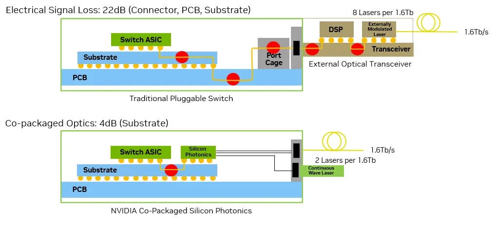
But where should the laser go in a co-packaged solution? The lowest loss and highest power savings will come from integrating the laser into the SiPho chip. But the industry has intentionally avoided doing that, instead choosing to keep the laser external to the rack as shown in the CPO solution above.
In the next few sections, we will discuss why this less optimal configuration was chosen, and how it is a better path for practical deployment of CPO. The answer lies in the fundamental physics of how temperature affects laser operation.
Temperature Sensitivity in III-V Laser Wavelength
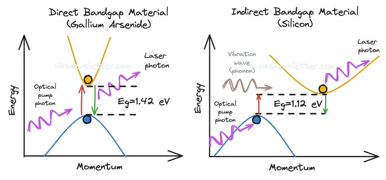
To understand why lasers are sensitive to temperature, we need to understand that laser action occurs in direct bandgap semiconductors that are mostly found only in III-V compound semiconductors like Indium Phosphide (InP). Silicon cannot produce laser light efficiently, which is why photonics chips need separate III-V based laser sources in the first place. If you want to understand why silicon fails as a laser material, I covered this in detail in an earlier post below.
Why We Can't Build Lasers on Silicon

Silicon technology has dominated for decades for its low cost and ability to scale, but it has its Achilles heel: you can’t build lasers on silicon.
The laser wavelength depends on the band gap energy (Eg) between the valence and conduction bands in the semiconductor. When temperature rises, electrons gain thermal energy and the band gap shrinks. A smaller band gap means longer wavelength output, i.e., a “red-shift” towards the red end of the spectrum.
For example, in an InP distributed feedback (DFB) laser operating with 1310 or 1550 nm telecom wavelengths, there is approximately 0.1 nm/°C dependence of wavelength on temperature. This might sound small, but in wavelength division multiplexing (WDM) systems where multiple optical channels are packed closely together, even small wavelength shifts can cause channel interference and data errors.
Impact of Temperature on Lasing Threshold and Efficiency
Temperature increases the lasing threshold current - the minimum drive current needed to achieve laser action and produce coherent light output. At higher temperatures, energy gets diverted into competing processes like carrier leakage and Auger recombination rather than stimulated laser emission. Unless you significantly increase the drive current to compensate, the laser’s output power will drop.
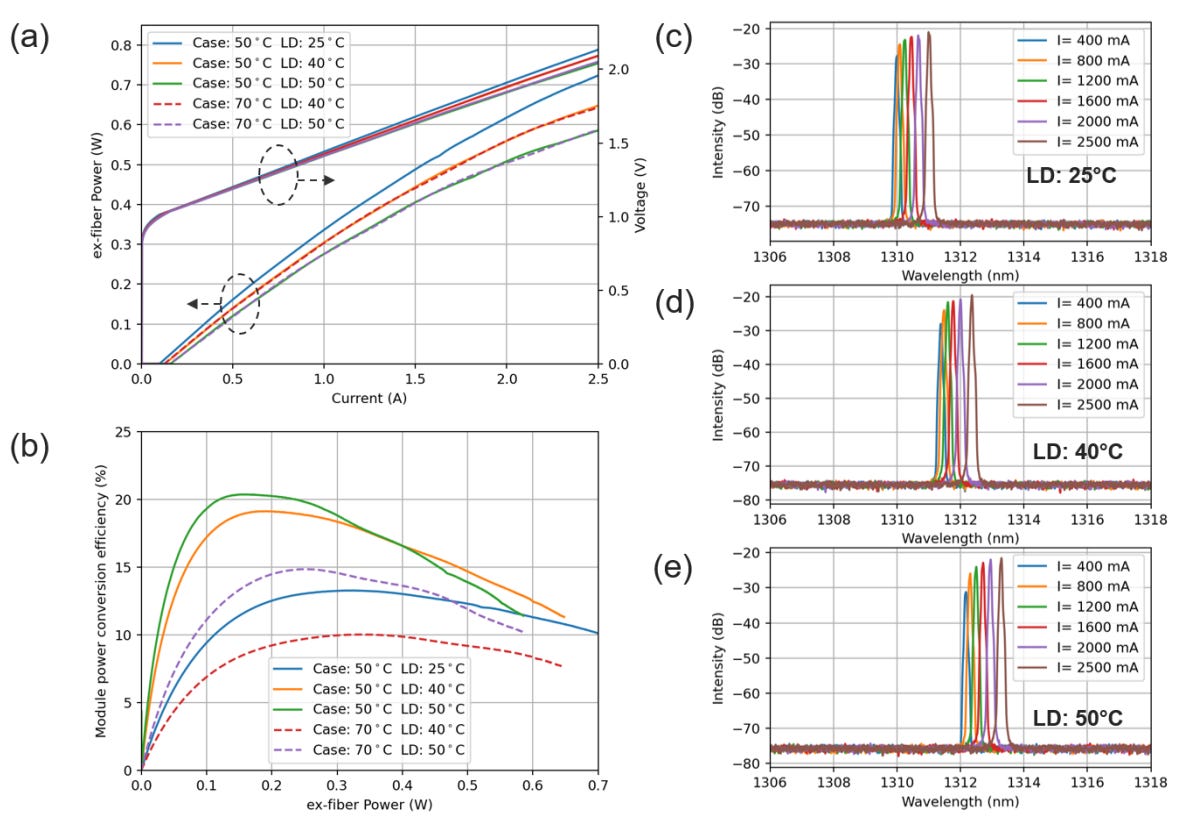
The plot below shows all these effects in a commercial InP DFB laser from Lumentum. As the junction temperature in the DFB laser diode (DFB) rises from 25°C to 50°C:
The threshold current increases and the output power at a given drive current decreases (inset a: left axis)
The laser wavelength shifts to higher values (insets c, d, e: case temperature is 50°C)
The conversion efficiency (inset b) is plotted for a constant fiber power of 0.4W, which requires different drive currents. As a result, it appears that efficiency gets better as the laser source gets hotter (increasing LD). However, for a constant laser temperature (say LD=40°C), increase in ambient “case” temperature significantly drops the efficiency (solid orange versus dotted red).
Lifetime Degradation at High Temperatures
High temperatures also destroy laser lifetime. The degradation follows Arrhenius-type relationships where device life decreases exponentially as temperature rises. The modeled plot below shows probability density functions for laser failure at different operating temperatures.
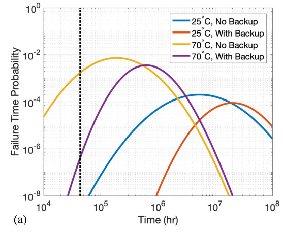
This plot means that if you tested 1000 laser components to failure at any given temperature, most would fail near the peak of the curve shown for that temperature. A few unlucky units fail early and a few lucky ones survive unusually long, representing the tail ends of each curve. The dotted vertical line marks the 5-year lifetime target that switch ASICs are typically rated to achieve. The curves show that temperature rise causes orders of magnitude reduction in laser lifetimes. It is quite common that operating a laser at 85°C instead of 25°C could result in the devices failing 10 times sooner.
The thermal challenge in laser sources involves maintaining them at temperatures where they can survive the multi-year operational lifetimes required for practical datacenter deployment.
For paid subscribers:
Laser Failure Rates: Field data from hyperscale datacenter operations
Solving the CPO Serviceability Problem with ELSFP: How external laser modules preserve hot-swap capability
InP Distributed Feedback Lasers for CPO: The laser technology used in production CPO systems
CPO Measured Reliability Performance: Lab stress test data from Broadcom
Laser sources: Key players: Best solutions for external lasers, and evolving ones