How Cracked Engineers Recreated World-Class RF Research in 30 Hours on Social Media
This is what happens when an esoteric RF circuit is revolutionized and becomes all the rage on X.
Welcome to the weekday free-edition of this newsletter that is a small idea, an actionable tip, or a short insight that takes less than 5 minutes to read. If you’re new, start here!
One of the more interesting themes at the 2025 International Microwave Symposium was the steady rise of AI/ML-driven design flows for RF circuits. I put together a detailed conference report that explains these developments that you can read below.
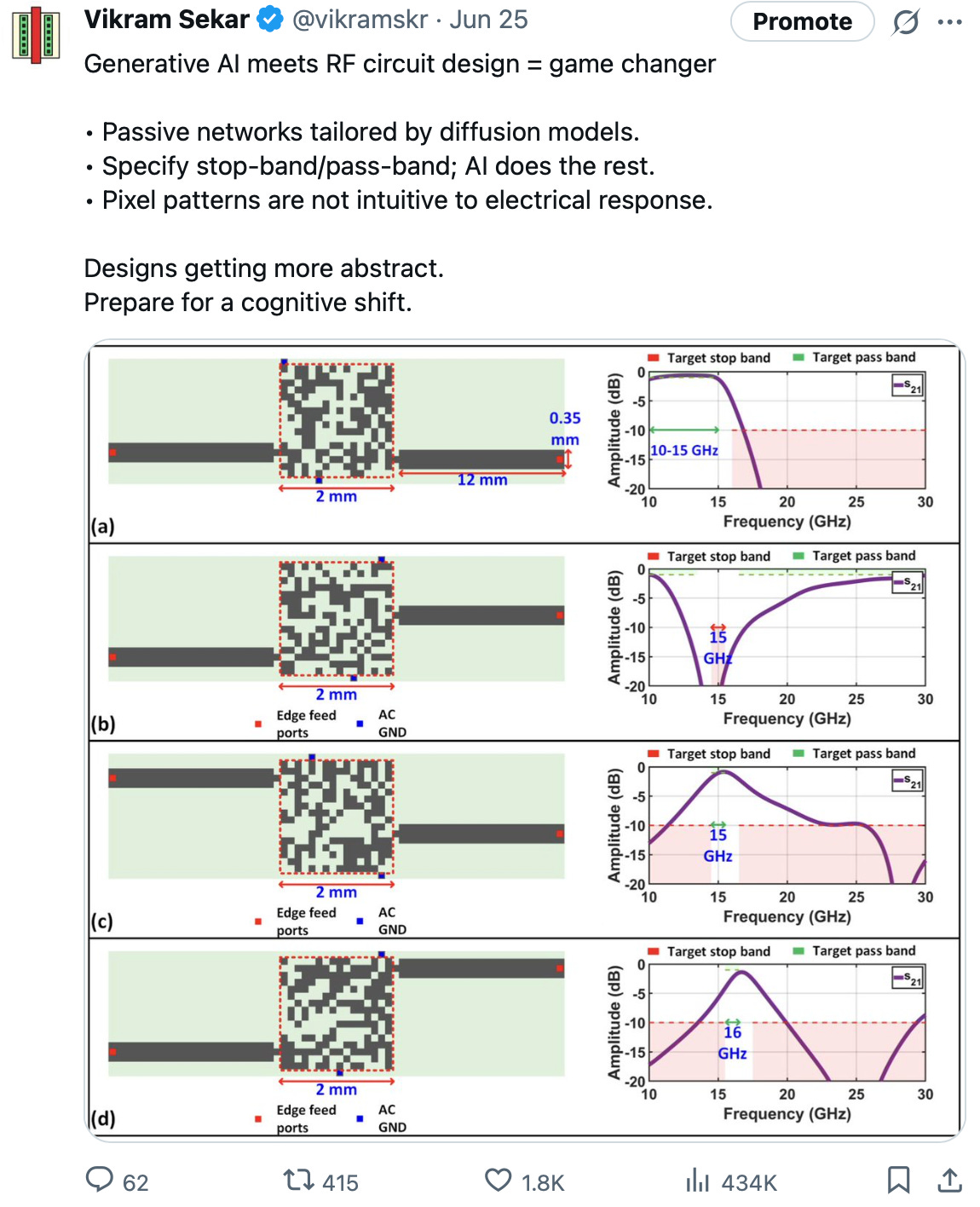
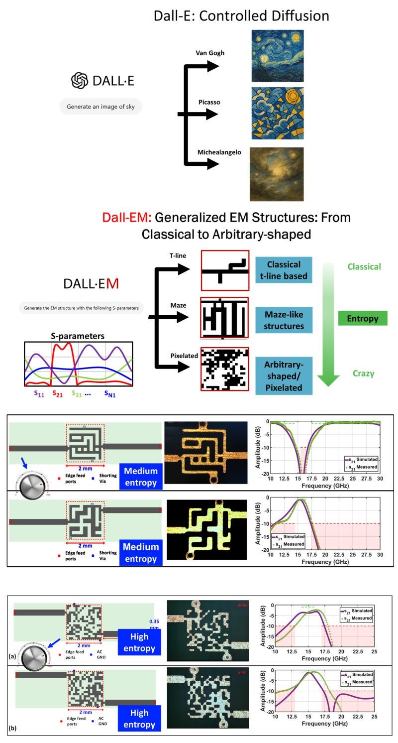
What really stood out was the application of diffusion models to synthesize passive networks with arbitrary electrical responses — a project called DALL-EM from Princeton University.
I shared some of their layouts on X because these entirely AI-generated structures achieved remarkably practical electrical responses. It was clear this work struck a chord with far more people than just me. That post ended up pulling in nearly half a million impressions, which is hardly something I would expect for an esoteric post on RF filters!
The beauty of the internet is that the original experts, like Prof. Kaushik Sengupta from Princeton University, noticed the virality of his work on social media and posted the following, providing more information to all those who are interested.
I got a flood of requests asking for the original paper — which, of course, I cannot share without the authors’ or IEEE’s permission. But the sheer enthusiasm from people wanting to understand how this works, and how they might recreate these results themselves, was unmistakable.
However, lack of the paper or references did not stop some on the internet from doing what they could anyway. Within a couple of hours of my X post, user Outside Five Sigma (OFS) on X recreated these results in simulation (you should also check out their blog for content that’s just far out!)
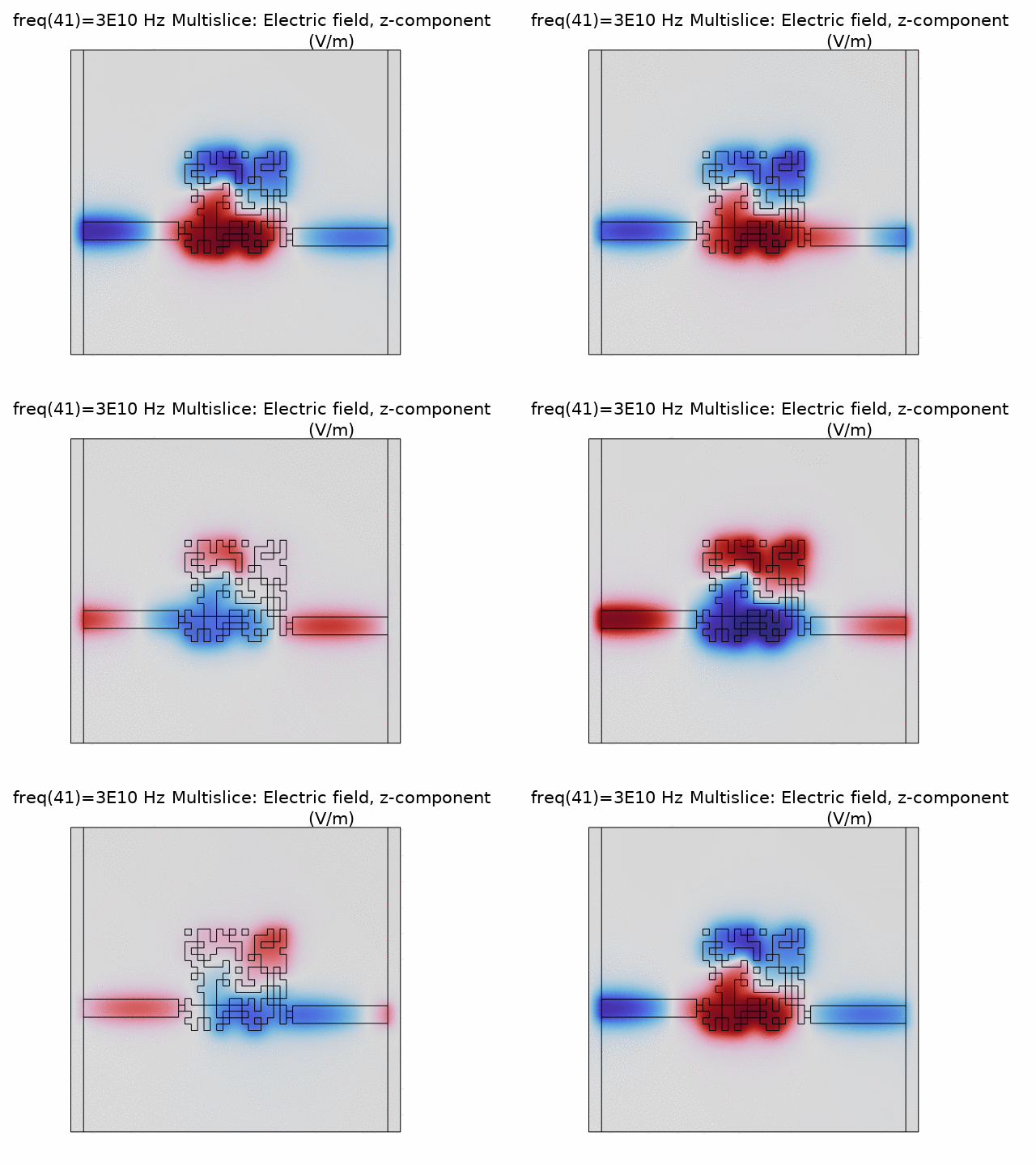
OFS uploaded the paper images I posted on X into Claude, and then asked it to generate a DXF file that could be brought into COMSOL for EM simulation. The code to convert images to DXF format was vibe-coded on Claude with specific inputs to make it work. You can see the code here. When there was no mention of the dielectric substrate on the X post, they simply assumed FR4 for microstrip-type structures, which is a perfectly reasonable guess.
And voila! A simulation of the pixelated structure confirming a low-pass response that was shown in the paper, and the added bonus of field plots. The figures below show a broadband simulated response of the filter and gif animations (courtesy of OFS’s GitHub) of the electric field at 30 GHz.
Another user on X did the same thing with CST microwave studio. There are other examples of similar recreations that have been popping up on LinkedIn in the past week too. This is great and I might have accidentally convinced Prof. Sengupta to create an X account and join the party! 😅
The next step is for someone to actually implement this filter in hardware and test it in a lab. That’s exactly what X user kuwahara82 did. The structure was made on Megtron 6 substrate because that’s simply what they had on hand. They eyeballed the layout and even missed some finer details in the original structure like shorting vias. Regardless, the results were promising to say the least.
Here is a better look at the measured response from this prototype filter.
From the time I posted on X, the total time including simulation, hardware implementation and measurements took about 30 hours and a few people from multiple continents. X may be a platform that has its downsides, but when you run into an awesome little niche, full of awesome people doing awesome stuff, it is more than rewarding to say the least.
Here are some comments I collected from social media. No need to perform sentiment analysis. 😆
Give or take 5 years until AI can gen a rickroll filter circuit
Daily reminder that RF is black magic
High frequency RF design is 75% voodoo
RF Engineers out of a job...
What the f
i would rather kill myself than become an rf engineer
me and the boys the last night before the deadline adding pure nonsense to the cavity design until it fits the band
This is utterly nuts. Alien technology nuts.
10GHz+ circuits are driven by magic anyway... Now you are arguing just which particular school of magic...
oh my god this is the most crazy thing i've seen...
It’s a great time to be alive!


This is crazy (in a good way)! Following for more.
Flagged this for the next issue—super interesting.