
Power Delivery As The Next Physics Wall In AI Datacenters
The physics forcing the 800V transition, conversion architectures that follow from it, and the power semiconductor sockets that emerge

One of the easier architectural changes to spot in AI datacenters are those that are physics-driven. Just like how copper interconnect reach was ultimately limited by losses, power delivery has a remarkably similar constraint: resistance.
Power density in a datacenter is an important metric for two reasons:
Land usage: There are geographical, environmental, social, and economic limitations to how big a datacenter campus can be. Beyond that limit, multi-datacenter campuses become necessary which complicates infrastructure.
Networking complexity: It is better to put as much compute in a single rack as possible so that networks span short physical distances, for which copper will suffice. Spanning different racks, buildings, or campuses increases power cost due to the need for optics at different levels, or active electronics for copper interconnects.
In an earlier article, we covered why datacenters need to shift to 800V DC in quite some depth, including an in-depth discussion of electrical systems in datacenter campuses.

What may not be obvious is that deploying high voltage datacenters is not as simple as retrofitting existing buildouts; true high voltage infrastructure needs greenfield buildouts. This is why early implementations of HVDC architectures by OCP Mt. Diablo and Nvidia’s Kyber rack have DC sidecar racks that handle 800V power supplies instead of natively routing it through the datacenter.
The essence of power delivery to a datacenter relies on keeping voltages as high as possible, for as long as possible, before it is delivered to a GPU. There are good physics reasons for this, which we will cover.
The question of how to generate power, where to convert the voltage, what kinds of devices are needed to do so, what is the most efficient method, and what is the most scalable approach as power in datacenters continuously increases, is where the whole discussion lies.
Several notable analysts are pointing out that power delivery is becoming increasingly important. Recently Wood Mackenzie reported that there is a structural shift in the demand for electrification, and a string of shortages in the supply chain. ON Semi CEO stated that power semi content will be 10x with the move to 800V DC racks, with additional semi content in power conversion outside the rack. Notable analysts like SemiAnalysis and Citrini Research are also pointing out that the “power plumbing” of AI datacenters, while seemingly boring, is showing a real inflection point in demand.
In this post, we will map out the landscape of power semiconductors. We will not cover power generation, industrial hardware, and delivery systems at the grid level here, or even outside the rack; that is a different discussion. We will look at the physics reasons for higher voltages, voltage conversions within the rack, and the engineering trade-offs in doing so. Finally, we will identify which architecture wins in the near and longer terms.
We will cover:
Power physics that forces the rethink
Power conversion architectures
Which 800V architecture wins
If you are not a paid subscriber, you can purchase just this article using the button below. You can find the whole catalog of articles for purchase at this link.
Power Physics that Forces the Rethink
It’s instructive to draw parallels between power and interconnects.
The reason optics is becoming increasingly popular is because skin-effect in copper wires increases its resistance. This is an effect that occurs when alternating currents flowing through a wire only utilize the periphery and not the entire cross section of the metal wire. This gets progressively worse as the speed of the signal increases. Optics is immune to this effect because light propagates through glass fibers; electrons and metals are not involved.
The consequences of interconnect physics in copper and optics is that you want to stay in the optical domain as long as possible, and convert to electrons as close to the chip as possible – this is the fundamental idea behind co-packaged optics, or CPO.
Now let’s turn to power.
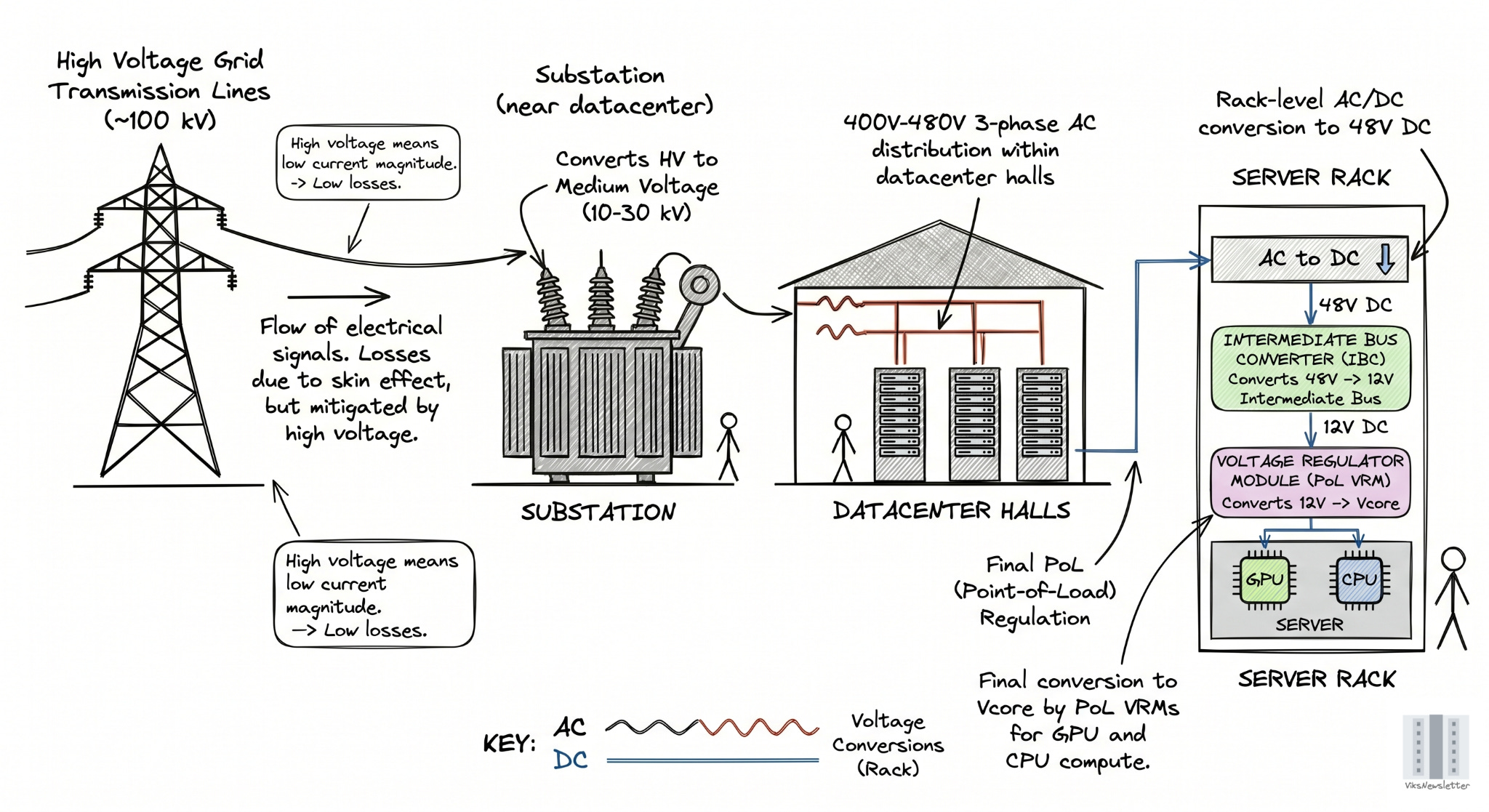
When electrical signals flow through grid transmission lines, they have losses due to skin effect too. But this can be mitigated by using high voltage lines often in the 100 kV range for power transmission. This ensures that the currents flowing are low in magnitude, thereby resulting in lower losses. The power is converted to medium voltage (10-30 kV) only at the substation in a datacenter, and distributed at 400-480V 3-phase AC within the datacenter halls. AC is converted to DC at the rack level to 48V by the power supply units (PSUs), then down to 12V by intermediate bus converters (IBCs), and finally down to 0.8V-1V by voltage regulator modules (VRMs).
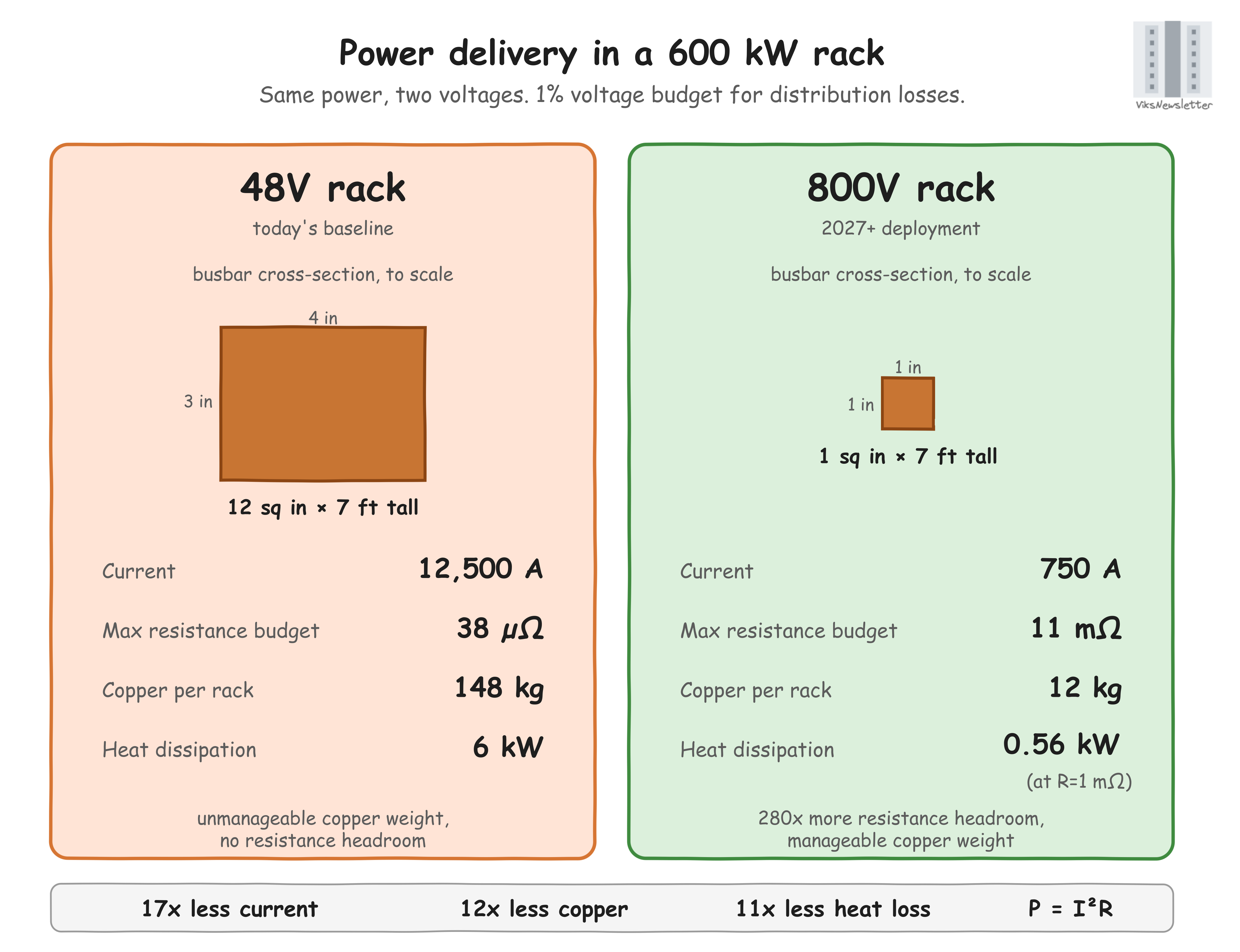
The rack scale voltage of 48V is important. To deliver P=600 kW (rating of the Kyber rack used to house the Rubin Ultra) at V=48V requires I=12,500A of current (P=VI). This level of current has serious implications.
Resistance headroom: If only 1% of the voltage budget (1% of 48V = 0.48V) should be lost to power delivery, then the total resistance from the rack PSU to load should be 0.48V/12,500A = 38 micro-ohms (R=V/I). This covers the busbar, joints, connectors combined, leaving no headroom; that resistance is already very low.
Copper weight: Busbars are thick metal buses that carry current, and practically supports about 1,000A/sq. in, before heating becomes a problem. For 12,500A, the cross-section of copper needs to be 12 sq. in (say 4” x 3”) that runs a full rack height of 7’. This puts the copper busbar volume at ~1,000 cubic inches per rack. Assuming copper density of 147 g/cu. in, each busbar then weighs 147 kg/rack. The cost and weight of this much copper is unmanageable.
Power dissipation: The power dissipated by this much current is I2R, which means that a linear increase in current results in quadratic power losses. With 12,500A of current and 38 micro-ohms of resistance, the power dissipated is 6 kW, which requires significant cooling efforts.
One way to greatly mitigate all these problems is to move to higher DC voltages like 800V.
At this voltage, 600 kW of power needs only 750A of current in the rack. 1% voltage budget leaves 8V/750A ~ 11 milli-ohms, which is much better headroom than micro-ohms. Copper busbars can be 1” x 1” and still support up to 1,000A. Busbar volume drops to 84 cu in, or 12.3 kg/rack which is much more manageable. Power dissipation assuming 1 milli-ohm resistance (25x worse than 38 micro-ohm case) is 0.56kW, which is much 1/10th of the 48V case, and better to handle cooling-wise.
All these numbers show one important implication: use high voltages as long as possible, before converting to lower voltages near the chip.
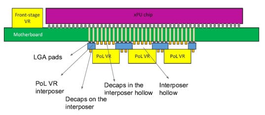
Just like optics has CPO, the equivalent in power delivery is called “Point-of-Load” (PoL), where only specific implementation is called Vertical Power Delivery (VPD). The main idea is to convert the high voltage to low voltage, right under the GPU where it is actually used.
How exactly voltage is converted from the 48V or 800V down to 0.8V required by GPUs is where all the engineering lies, and is what defines the entire competitive space of power semiconductors in AI datacenters at the rack level. Now that we have established why higher voltages are necessary, the next question is how to step down efficiently from 800V or 48V to the GPU core voltage.
Power Conversion Architectures
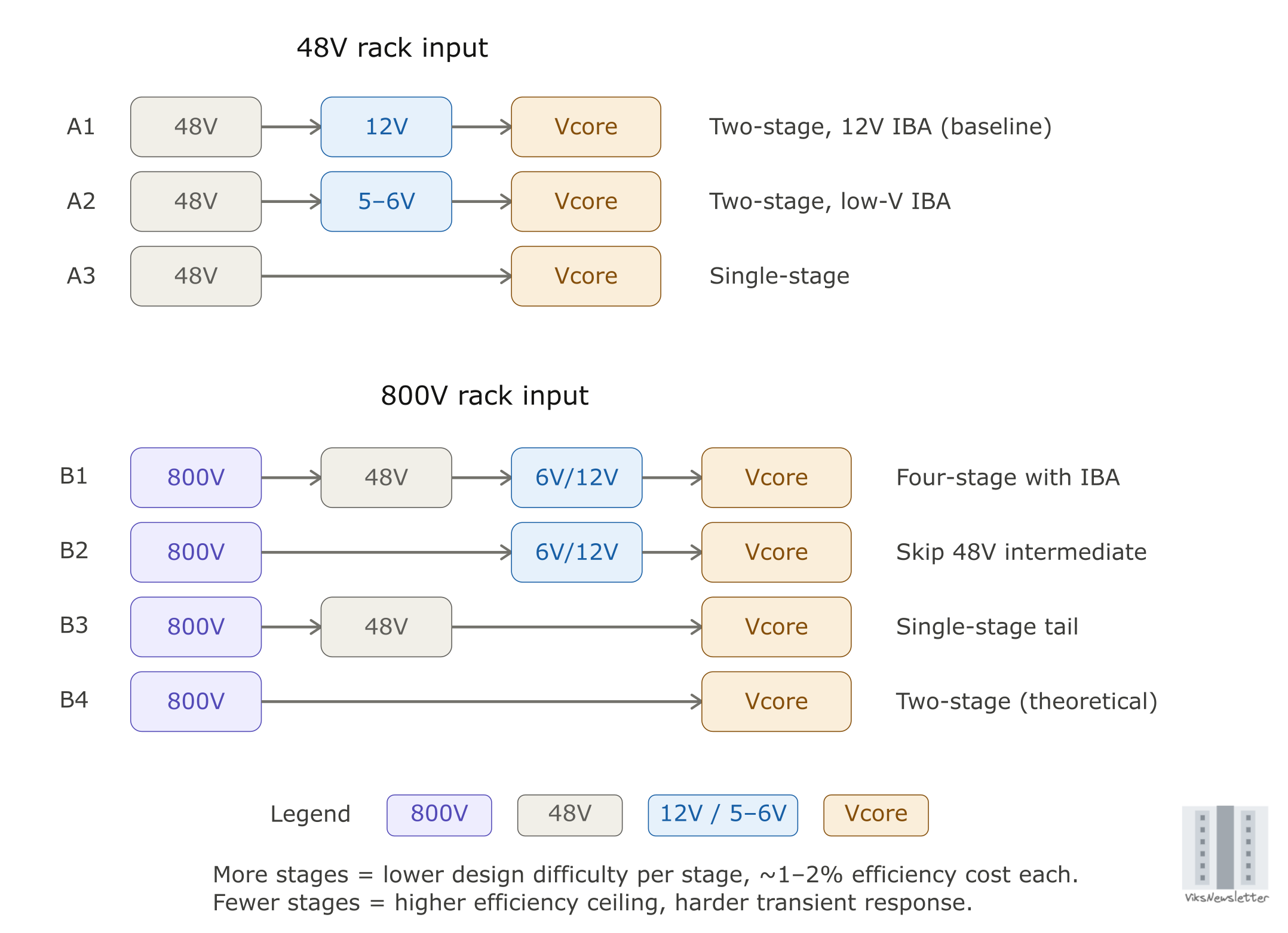
The power conversion architectures at 48V and 800V are shown below. These do not cover every possibility, but are sufficient to understand the trade-offs in each case. For each architecture, the number of conversion stages and voltage choices at each stage determine the overall efficiency, cost, and dynamic behavior of the power conversion. The 12V or 5-6V stages in blue are often called Intermediate Bus (IB) voltages. We will discuss these trade-offs at a high level.
Number of conversion stages
Every stage of power conversion has some power loss, and hence fewer conversion stages means lower loss, to the first order. Even a 97% conversion at each stage results in a 91% overall efficiency for a 3-stage power convertor. The per-stage conversion efficiency depends on the actual voltage values at the input and output, and efficiency of each stage need not be the same. This is overall a simple concept: fewer stages, lower loss, higher efficiency. So why not just convert all voltages in a single stage?
Voltage Levels and Conversion Ratio
Every stage of voltage conversion typically uses a completely different kind of converter, which implies that there are different companies that capture varying amounts of value depending on the power conversion architecture being deployed. The output to input voltage ratio and the actual voltage values drive circuit topology choice.
Three constraints determine the voltage levels and the topology choice at each stage: isolation requirements, conversion ratio efficiency, and the need for tight voltage regulation at the final stage.
1) Isolation and the SELV threshold
SELV stands for Safety Extra-Low Voltage. The IEC 61140 standard defines a SELV circuit as one where the voltage between any two conductors, or between any conductor and earth, does not exceed 60V DC (often used in practice even if spec is higher) under normal and single-fault conditions. Below this threshold, current through a person making direct contact is unlikely to be fatal. Above it, the circuit must be galvanically isolated from any electrical conductor a human can touch, which usually means a transformer separating the primary and secondary sides of the converter (these are magnetically coupled, and have no wires from input to output, which isolates them galvanically).
This is why 48V and 54V rack voltages exist where they do because they sit just below the SELV ceiling. Anything downstream of the 48V busbar can be non-isolated, which removes the transformer from the converter and saves space, cost, and a percentage point or two of efficiency.
For architecture, the rule is simple. Any conversion stage with input above 60V DC needs an isolated topology. AC line to 48V is isolated. 800V to 48V is isolated. Once at 48V or below, no further isolation is needed, and the rest of the chain runs on non-isolated converters.
Beyond isolation, two more constraints determine which converter sits at each stage and which vendors compete for that socket. These constraints, and how they map to the 800V architectures, are where the investment thesis lives.